-
×
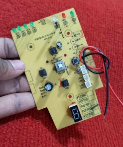
 F0178D Charger Fan Circuit AC DC Fan Circuit For AC DC Charger Fan AC DC Rechargeable Fan Circuit With Digital LED Display PWM Fan Speed Control LED Lamp ON OFF Functionality Included
2 × ৳ 350.00
F0178D Charger Fan Circuit AC DC Fan Circuit For AC DC Charger Fan AC DC Rechargeable Fan Circuit With Digital LED Display PWM Fan Speed Control LED Lamp ON OFF Functionality Included
2 × ৳ 350.00 -
×
Breakout Board USB Type B Female Socket Breakout Board 2.54mm Pitch Adapters Connector USB-B To DIP 4 Pin USB B Test Board USB Mother Seat To DIP
1 × ৳ 45.00
-
×
KA2206 KA2206B DIP12 Dual Audio Power Amplifier DIP-12 Audio Amplifier Speaker Power 2-Channel KA2206 Audio Power Amplifier Chip 12 Pin Leads
1 × ৳ 35.00
-
×
SILVER Color 900M-T-K Soldering Tip Bit Leads Free Soldering Iron Bits Replacement Pencil Soldering Solder Iron Tip For Soldering Iron & Station Tools Tip
1 × ৳ 35.00
-
×
Brass COPPER 900M-T-K Soldering Tip Bit Leads Free Soldering Iron Professional Bits Replacement Pencil Soldering Solder Iron Tip For Soldering Station & Iron Tip
1 × ৳ 99.00
-
×
47K Resistor 47K Ohm Carbon Film Resistor 47K 1/4W Resistance 0.25 Watt 5% Tolerance Fixed Resistors
50 × ৳ 0.30
-
×
Tolerance 1% 560K Ohm COPPER Resistor 560k Ohm Carbon Film Resistor 560k Ohm 1/4W Resistance 0.25 Watt Fixed Resistors Passive Components Parts
50 × ৳ 0.70
-
×
Tolerance 1% 330K Ohm COPPER Resistor 330k Ohm Carbon Film Resistor 330k Ohm 1/4W Resistance 0.25 Watt Fixed Resistors Passive Components Parts
50 × ৳ 0.70
-
×
Tolerance 1% 150K Ohm COPPER Resistor 150k Ohm Carbon Film Resistor 150k Ohm 1/4W Resistance 0.25 Watt Fixed Resistors Passive Components Parts
50 × ৳ 0.70
-
×
Tolerance 1% 120K Ohm COPPER Resistor 120k Ohm Carbon Film Resistor 120k Ohm 1/4W Resistance 0.25 Watt Fixed Resistors Passive Components Parts
50 × ৳ 0.70
-
×
Tolerance 1% 82K Ohm COPPER Resistor 82k Ohm Carbon Film Resistor 82k Ohm 1/4W Resistance 0.25 Watt Fixed Resistors Passive Components Parts
50 × ৳ 0.70
-
×
1/2 Watt 1K Ohm Resistor 1/2W 1K Ohm Carbon Film Resistor 1K Ohm Half Watt Resistance 0.5 Watt 5% Tolerance Fixed Resistors Passive Components 2 Pin Leads Terminals
25 × ৳ 0.60
-
×
Tolerance 1% 10K Resistor 10K Carbon Film Resistor 10K Ohm Resistor 1/4W Resistance 0.25 Watt Fixed Resistors 2 Pin Leads
50 × ৳ 0.45
-
×
 1M Ohm Resistor 5% 1M Ohm Carbon Film 1M Ohm Resistors 1/4W Resistance 0.25 Watt 5% Tolerance Fixed Resistors 2 Pin Leads
50 × ৳ 0.30
1M Ohm Resistor 5% 1M Ohm Carbon Film 1M Ohm Resistors 1/4W Resistance 0.25 Watt 5% Tolerance Fixed Resistors 2 Pin Leads
50 × ৳ 0.30 -
×
4P USB Female Breakout Board USB 2.0 Mother Seat To DIP 4 Pin USB Type A USB Female Socket Breakout Board 2.54mm Pitch Adapters Connector DIP DIY USB Power Supply Breadboard Design
1 × ৳ 45.00
-
×
Card Reader PLASTIC BODY Mini SD Memory CARD READER For USB Devices Computer Laptop Notebook PC Desktop MP3 MP5 Player Audio Video Player
1 × ৳ 20.00
 F0178D Charger Fan Circuit AC DC Fan Circuit For AC DC Charger Fan AC DC Rechargeable Fan Circuit With Digital LED Display PWM Fan Speed Control LED Lamp ON OFF Functionality Included
 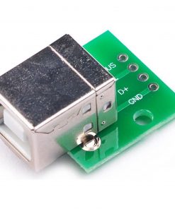 Breakout Board USB Type B Female Socket Breakout Board 2.54mm Pitch Adapters Connector USB-B To DIP 4 Pin USB B Test Board USB Mother Seat To DIP
  KA2206 KA2206B DIP12 Dual Audio Power Amplifier DIP-12 Audio Amplifier Speaker Power 2-Channel KA2206 Audio Power Amplifier Chip 12 Pin Leads
  SILVER Color 900M-T-K Soldering Tip Bit Leads Free Soldering Iron Bits Replacement Pencil Soldering Solder Iron Tip For Soldering Iron & Station Tools Tip
  Brass COPPER 900M-T-K Soldering Tip Bit Leads Free Soldering Iron Professional Bits Replacement Pencil Soldering Solder Iron Tip For Soldering Station & Iron Tip
  47K Resistor 47K Ohm Carbon Film Resistor 47K 1/4W Resistance 0.25 Watt 5% Tolerance Fixed Resistors
  Tolerance 1% 560K Ohm COPPER Resistor 560k Ohm Carbon Film Resistor 560k Ohm 1/4W Resistance 0.25 Watt Fixed Resistors Passive Components Parts
  1/2 Watt 1K Ohm Resistor 1/2W 1K Ohm Carbon Film Resistor 1K Ohm Half Watt Resistance 0.5 Watt 5% Tolerance Fixed Resistors Passive Components 2 Pin Leads Terminals
  Tolerance 1% 10K Resistor 10K Carbon Film Resistor 10K Ohm Resistor 1/4W Resistance 0.25 Watt Fixed Resistors 2 Pin Leads
 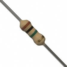 1M Ohm Resistor 5% 1M Ohm Carbon Film 1M Ohm Resistors 1/4W Resistance 0.25 Watt 5% Tolerance Fixed Resistors 2 Pin Leads
 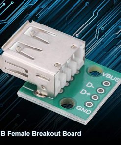 4P USB Female Breakout Board USB 2.0 Mother Seat To DIP 4 Pin USB Type A USB Female Socket Breakout Board 2.54mm Pitch Adapters Connector DIP DIY USB Power Supply Breadboard Design
 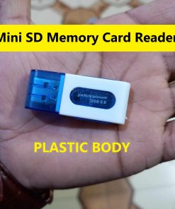 Card Reader PLASTIC BODY Mini SD Memory CARD READER For USB Devices Computer Laptop Notebook PC Desktop MP3 MP5 Player Audio Video Player
 Subtotal: ৳ 1,221.50


Reviews
There are no reviews yet.