


TB6600 Stepper Motor Driver Controller DC 9-42V 4A TB6600 Stepper Motor Driver 4A 42VDC Motor Driver Adapters For CNC Machine 3D Printer DIY
৳ 899.00
Stepper Motor Driver Controller TB6600 DC 9-42V 4A For CNC Engraving Machine 3D Printer DIY Electronics Project TB 6600
Description: TB6600 9-42V 4A Stepper Motor Driver Controller
TB6600 Stepper Motor Driver Controller DC 9-42V 4A TB6600 Stepper Motor Driver 4A 42VDC Motor Driver Adapters For CNC Machine 3D Printer DIY
TB6600 arduino Stepper Motor Driver is an easy-to-use professional stepper motor driver, which could control a two-phase stepping motor. It is compatible with Arduino and other microcontrollers that can output a 5V digital pulse signal. TB6600 arduino stepper motor driver has a wide range power input, 9~42VDC power supply. And it is able to output 4A peak current, which is enough for the most of stepper motors.
The stepper driver supports speed and direction control. You can set its micro step and output current with 6 DIP switch. There are 7 kinds of micro steps (1, 2 / A, 2 / B, 4, 8, 16, 32) and 8 kinds of current control (0.5A, 1A, 1.5A, 2A, 2.5A, 2.8A, 3.0A, 3.5A) in all. And all signal terminals adopt high-speed optocoupler isolation, enhancing its anti-high-frequency interference ability.
As a professional device, it is able to drive 57, 42-type two-phase, four-phase, hybrid stepper motor.
Specifications:
- Input Current: 0~5A
- Output Current: 0.5~4.0A
- Control Signal: 3.3~24V
- Power (MAX): 160W
- Micro Step: 1, 2/A, 2/B, 4, 8, 16, 32
- Temperature: -10~45℃
- Humidity: No Condensation
- Weight: 0.2 kg
- Dimension: 96x 71×37 mm
Features:
- Recommended Power : 24-36V
- Support 8 kinds of current control
- Support 7 kinds of micro steps adjustable
- The interface adopts high-speed on to coupler isolation
- Large area heat sink
- Anti-high-frequency interference ability
- Input anti-reverse protection
- Overheat, over current and short circuit protection
- Output Current:0.5~4.0A
- Power (MAX):160W
- Micro Step:
- 1, 2/A, 2/B, 4, 8, 16, 32
Terminal definition Definitions:
Signal input:
- (1)CP +: pulse signal input positive side.
- (2)CP-: pulse signal input negative.
- (3)DIR +: motor positive, reverse control positive side.
- (4)DIR-: motor positive, reverse control negative.
- (5)EN +: motor offline control positive side.
- (6)EN-: motor off-line control negative.
Motor Winding Connection:
- (7) A +: Connect the motor winding A + phase.
- (2) A-: connect the motor winding A-phase.
- (3) B +: Connect the motor winding B + phase.
- (4)B-: Connect the motor winding B-phase.
Working Voltage Connection:
- (1) VCC: DC power supply positive (Note: 10V < VCC < 42V).
- (2)GND: DC power supply negative
There are two types of input signal interface:
Users can use the common anode connection or common cathode connection according to the need.
- 1. Common to the anode connection: CP +, DIR +, EN + will be connected to the control system power supply, if this power is +5 V can be directly connected, if the power is greater than + 5V, the external additional current limiting resistor R, To drive the internal light lotus to provide 8-15mA drive current. The pulse input signal is via CP-access; at this point, DIR-, EN- is active at low level.
- 2.Common cathode connection method: connect the CP-, DIR- and EN- to the ground of the control system (SGND, isolate from the power source); the pulse input signal of the +5V is added by CP+; at this time, the DIR+ and EN+ are active at high level. The connection value of current limiting resistor R is the same as common anode connection method.
Package Included:
- 1 x TB6600 9-42V 4A Stepper Motor Controller Motor Driver Controller For CNC Engraving Machine
Only logged in customers who have purchased this product may leave a review.
Related products


DC Motors & Drivers
Motor Control Shield Expansion Board with Dual H-bridge Driver L293D


DC Motors & Drivers
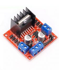
RED Color L298N Motor Driver Module Dual Channel H-Bridge L298N Motor Driver Shield L298N Module


Reviews
There are no reviews yet.