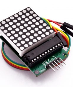
MAX7219 Display MAX7219 Dot Matrix Display Module For Arduino MAX7219 Microcontroller 8×8 Dot Display With 5 Pin Cables MAX7219 Display Dot Matrix LED
৳ 240.00
MAX7219 Dot Matrix Module For Arduino Microcontroller 8×8 Dot Display With 5 Pin Line MAX 7219 Display
Description: MAX7219 Dot Matrix Module
MAX7219 Display MAX7219 Dot Matrix Display Module For Arduino MAX7219 Microcontroller 8×8 Dot Display With 5 Pin Cables MAX7219 Display Dot Matrix LED
The 8×8 LED matrix displays are usually used for the display of symbols, simple graphics and texts. Made of super bright LEDs, they produce low resolution display and can be daisy chained to produce larger displays. To enable us to control the display easily, we will be using the MAX7219 LED display driver module. Although this driver comes attached to the LED Matrix display that we will be using for this tutorial, its important to treat them separately, so you can understand how the LED driver works and be able to use it in case you are unable to get an 8×8 LED Matrix display that comes with the LED Driver.
The MAX7219 are compact, serial input/output common-cathode display drivers that interface to microcontrollers and microprocessors to control 7-segment numeric LED displays of up to 8 digits, bar-graph displays, or 64 individual LEDs. Included on the MAX7219 chip is a BCD code-B decoder, a multiplex scan circuitry, a segment and digit drivers, and an 8×8 static RAM that stores each digit. Only one external resistor is required to set the segment current for all LEDs. Individual digits of the connected LED display may be addressed and updated without rewriting the entire display. The MAX7219 also allow the user to select code-B decoding or no-decode for each digit.
Pin Connection:
Dot LED Module to the Arduino
- Vcc – 5V
- GND – GND
- DIN – Pin 12
- CS – Pin 10
- CLK – Pin 11
Feature:
- Using MAX7219 control chip, integrated BCD encoder, scanning circuit and driving circuit
- Integrated static RAM, each data can be addressed without change all display when updating
- Integrated analog and digital brightness control, each dot display brightness consistent
- Inside chip integrated scan circuit, do not take up system resources
- Chip occupies only 3 IO port, you can cascade
Specification:
- Dimensions: 32 x 32 x 14mm
- Mounting holes: 3mm
- Pitch: 1000 * 1000mil (25.4 * 25.4mm)
- Color: Red
- Voltage: 5V
- Chip: MAX7219
- LED: 8 * 8 common cathode lattice, removable
- Port: SPI can cascade
- 1. VCC and GND is not reversed, it would burn the chip!
- 2. When the 51 microcontroller P0 port controlling, must be connected to the pull-up resistor, it is recommended that the resistance of 4.7K–10K
- 3. Please install lattice into the round hole first, and then insert the round hole to PCB board and weld. Face the side of lattice with words, from left to right pin order is 123456. PCB board 1st pin is square pad!
- 4.Electrolytic capacitors long-pin as positive, short-pin as negative; ceramic capacitor has no positive and negative points
Package Include:
- 1 x MAX7219 8×8 Matrix Module
- 1 x Connecting Wire
Only logged in customers who have purchased this product may leave a review.


















Reviews
There are no reviews yet.