
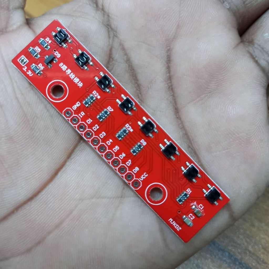

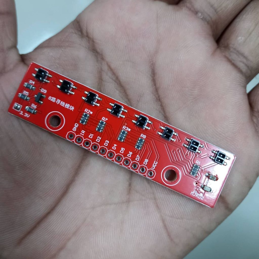
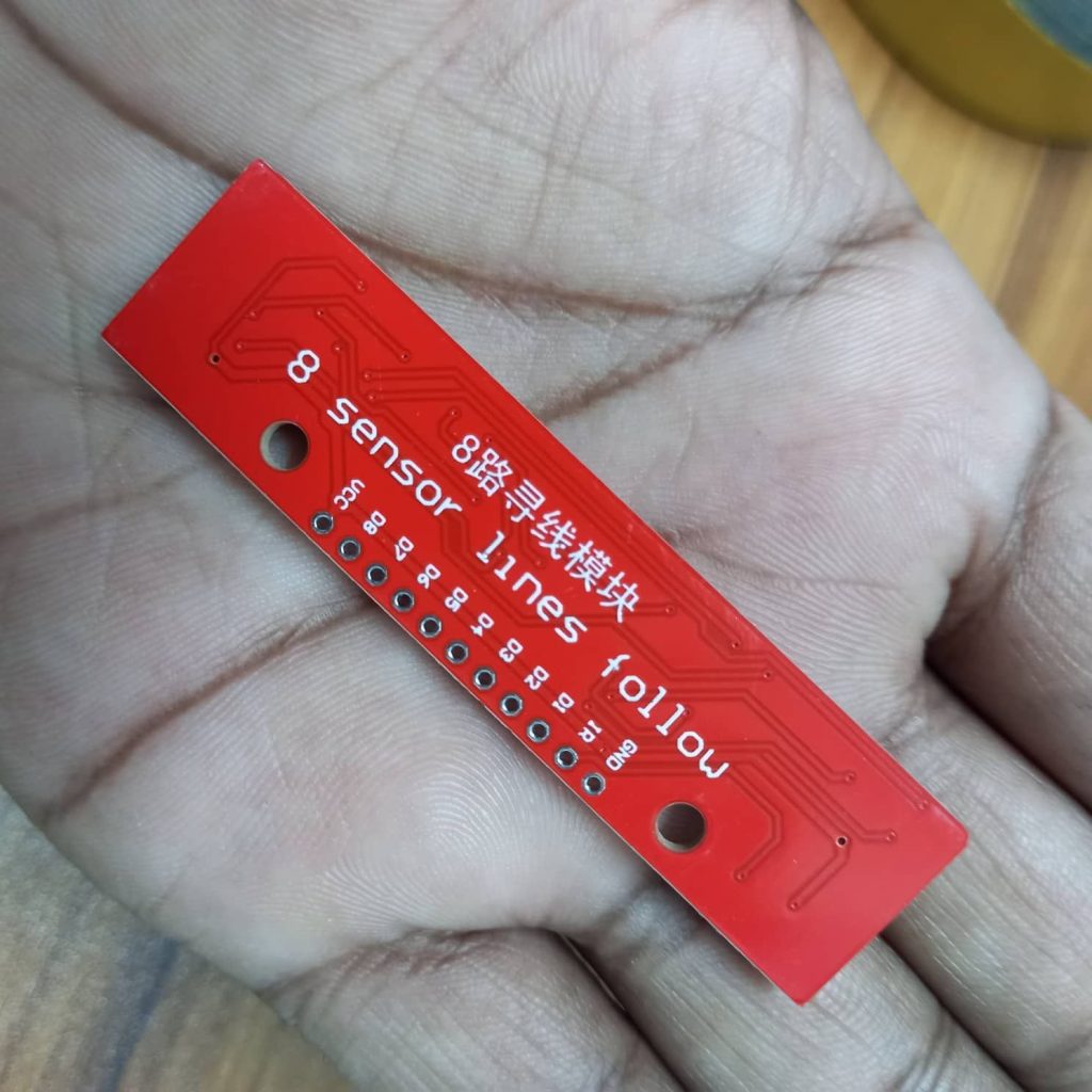
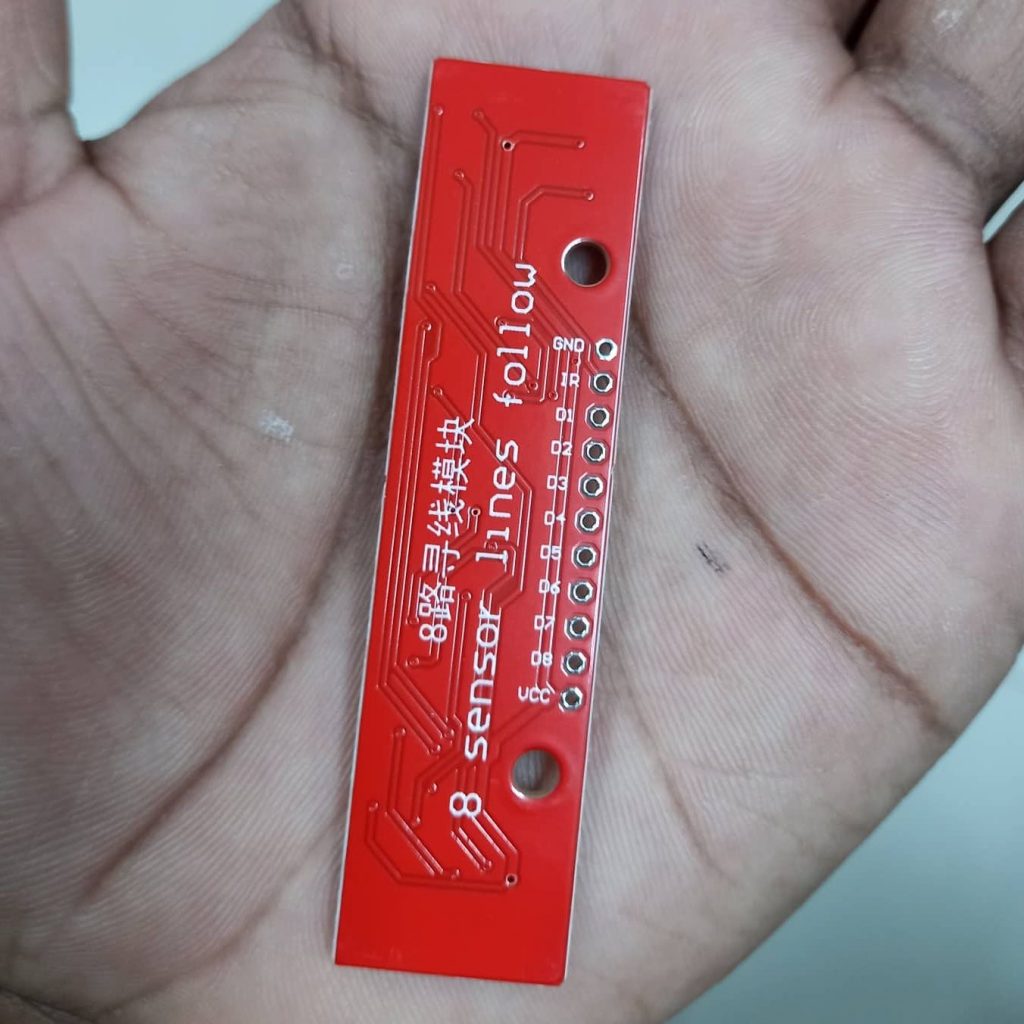


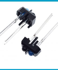
QTR-8RC 8 Channels Digital Infrared Reflectance Sensor Array QTR-8RC IR Infrared Line Tracking QTR 8RC 8 Channel Sensor Array HYS301 Line Following Sensor Module For Arduino
৳ 450.00
Digital QTR-8RC Infrared Reflectance Sensor Array QTR-8RC 8 Channel Digital IR Infrared Line Tracking Reflectance Line Following Sensor
Description: QTR-8RC Infrared Reflectance Sensor Array
QTR-8RC 8 Channels Digital Infrared Reflectance Sensor Array QTR-8RC IR Infrared Line Tracking QTR 8RC 8 Channel Sensor Array HYS301 Line Following Sensor Module For Arduino
Infrared Reflectance Sensor Array: fail-safe sensitivity, maximum energy savings This Infrared Reflectance Sensor Array’s two main qualities? First, its acuity, which is enhanced by its digital I/O-measurable output (more sensitive than an analogue output with voltage divider bridge). Then its lower energy consumption, thanks to its 8 pairs of infrared transmitters and sensors arranged in series and spaced at a maximum distance of 9.5 mm (effectively halving the sensor’s consumption).
It is also an extremely lightweight module, since it weighs barely more than 3 g. The MOSFET transistor equipping this sensor module can disable its infrared LEDs according to its needs, hence reducing its energy consumption accordingly at times when your project doesn’t require use of the sensor, or when it requires use of an infrared sensor alone.
Uses of the QTR-8RC Infrared Reflectance Sensor Array:
This QTR-8RC Infrared Reflectance Sensor Array is used mainly as a line sensor, making it the ideal module for a line-following robot. But it can also be used to detect objects, or even reflective surfaces. Note also that, depending on your project, it is possible to split this array of 8 sensors to obtain 6 sensors on the one hand and 2 on the other.
Technical specifications:
- Dimensions: 74.93 mm x 12.7 mm x 3.175 mm (without header pins)
- Operating voltage: 3.3–5.0V
- Supply current: 100 mA
- Outputs: 8 digital I/O compatible outputs that can be read as a timed high pulse
- Optimal sensing distance: 3 mm
- Maximum sensing distance: 9.5 mm
- Weight: 3.09 g (without header pins)
- Module supplied with 100 Ω resistor and connector
Features:
- In this sensor, no ADC is required.
- It has improved sensitivity over voltage-divider analog output.
- It has a parallel reading of multiple sensors is possible with most microcontrollers.
- Its parallel reading allows optimized use of LED power enables the option.
- Its operating voltages are 3.3 to 5V.
- Its supply current is 100mA.
- It has 8 digital input-output signals that can be read as a timed high pulse.
- Its optimal sensing distance is 0.125 inches.
- Its maximum sensing distance is 0.375 inches.
- On this sensor parallel reading of multiple sensors is possible
Functional Description:
The QTR-8RC reflectance sensor array is intended as a line sensor, but it can be used as a general-purpose proximity or reflectance sensor. The module is a convenient carrier for eight IR emitter and receiver (phototransistor) pairs evenly spaced at intervals of 0.375″ (9.525 mm). To use a sensor, you must first charge the output node by applying a voltage to its OUT pin. You can then read the reflectance by withdrawing that externally applied voltage on the OUT pin and timing how long it takes the output voltage to decay due to the integrated phototransistor. Shorter decay time is an indication of greater reflection. This measurement approach has several advantages, especially when coupled with the ability of the QTR-8RC module to turn off LED power:
- No analog-to-digital converter (ADC) is required
- Improved sensitivity over voltage-divider analog output
- Parallel reading of multiple sensors is possible with most microcontrollers
- Parallel reading allows optimized use of LED power enable option
The outputs are all independent, but the LEDs are arranged in pairs to halve current consumption. The LEDs are controlled by a MOSFET with a gate normally pulled high, allowing the LEDs to be turned off by setting the MOSFET gate to a low voltage. Turning the LEDs off might be advantageous for limiting power consumption when the sensors are not in use or for varying the effective brightness of the LEDs through PWM control.
This sensor was designed to be used with the board parallel to the surface being sensed.
The LED current-limiting resistors for 5 V operation are arranged in two stages; this allows a simple bypass of one stage to enable operation at 3.3 V. The LED current is approximately 20–25 mA, making the total board consumption just under 100 mA. The schematic diagram of the module is shown below:
The QTR-8RC module has eight identical sensor outputs that, like the Parallax QTI, require a digital I/O line capable of driving the output line high and then measuring the time for the output voltage to decay. The typical sequence for reading a sensor is:
Interfacing the QTR-8RC Outputs to Digital I/O Lines:
- Turn on IR LEDs (optional).
- Set the I/O line to an output and drive it high.
- Allow at least 10 μs for the sensor output to rise.
- Make the I/O line an input (high impedance).
- Measure the time for the voltage to decay by waiting for the I/O line to go low.
- Turn off IR LEDs (optional).
These steps can typically be executed in parallel on multiple I/O lines.
With a strong reflectance, the decay time can be as low as several dozen microseconds; with no reflectance, the decay time can be up to a few milliseconds. The exact time of the decay depends on your microcontroller’s I/O line characteristics. Meaningful results can be available within 1 ms in typical cases (i.e. when not trying to measure subtle differences in low-reflectance scenarios), allowing up to 1 kHz sampling of all 8 sensors. If lower-frequency sampling is sufficient, substantial power savings can be realized by turning off the LEDs. For example, if a 100 Hz sampling rate is acceptable, the LEDs can be off 90% of the time, lowering average current consumption from 100 mA to 10 mA.
Package Include:
- 1 x Digital QTR-8RC Infrared Reflectance Sensor Array QTR-8RC 8 Channel Digital IR Infrared Line Tracking Reflectance Line Following Sensor
Only logged in customers who have purchased this product may leave a review.
Related products


Microcontroller, ICs & Base


Microcontroller, ICs & Base


Reviews
There are no reviews yet.